






Product Overview and Core Positioning
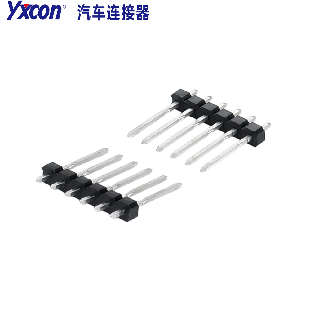
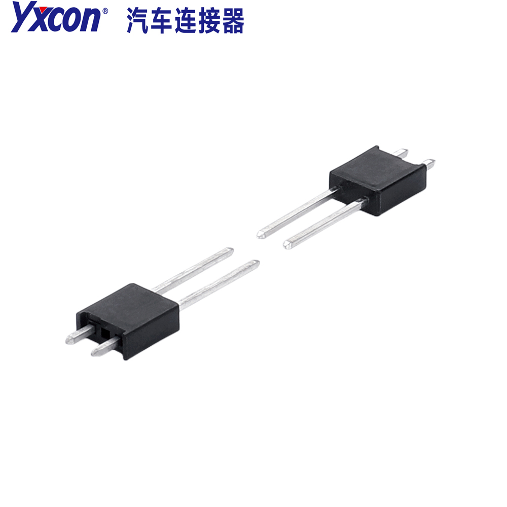
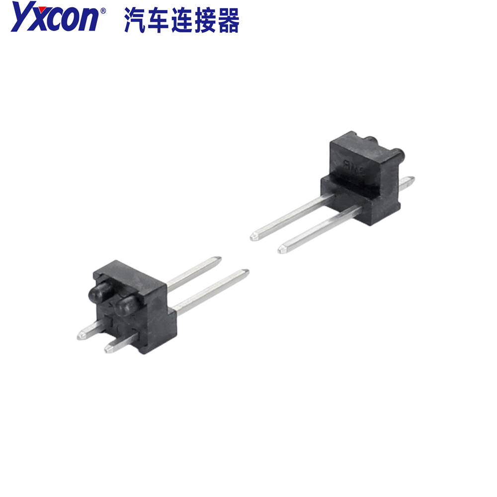
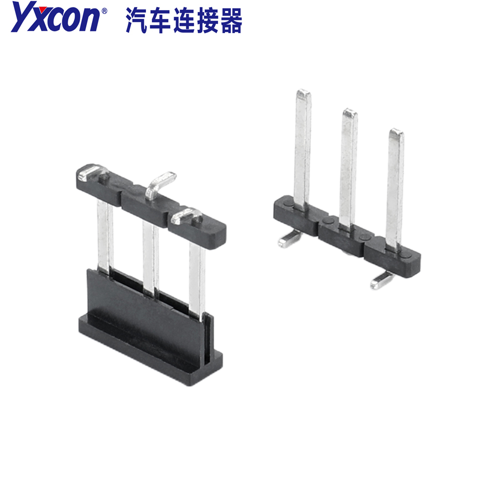
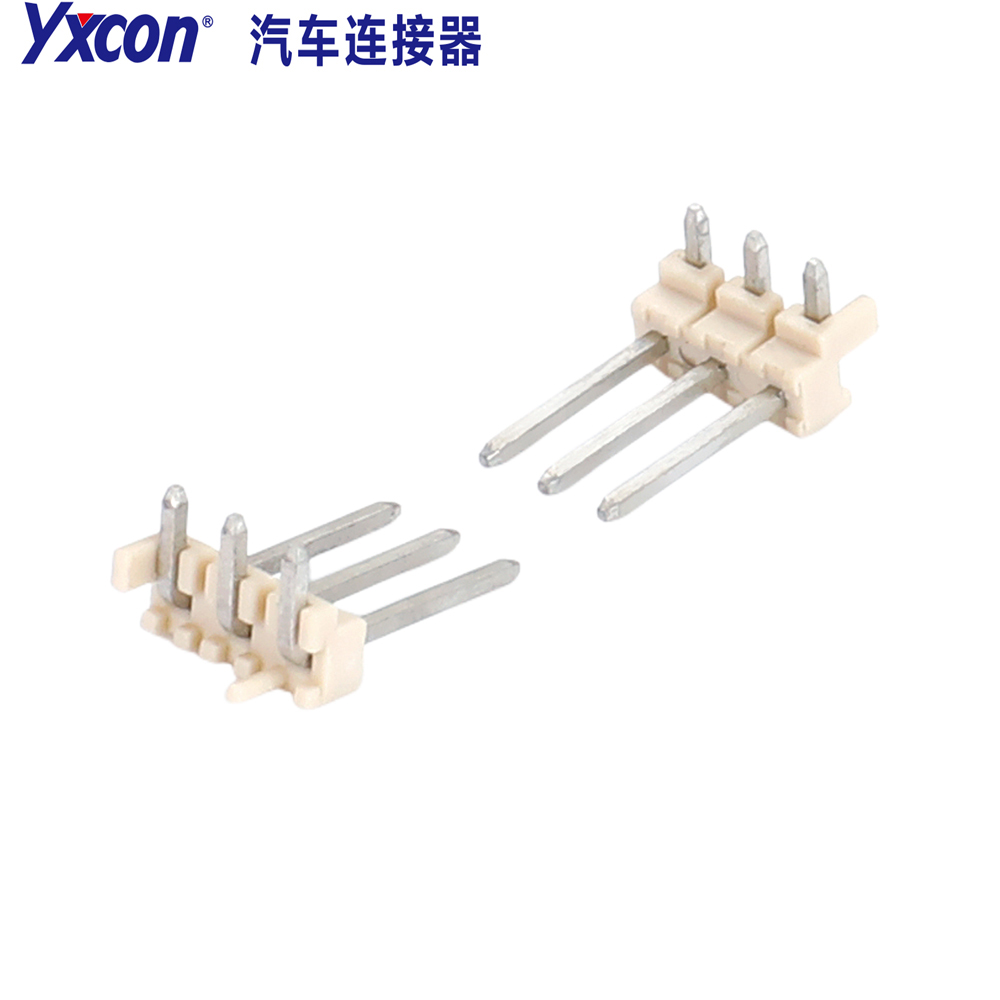
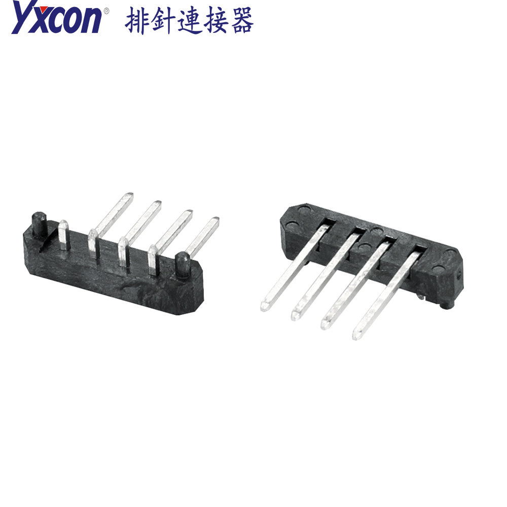
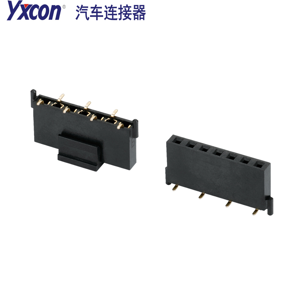
The FH2.54-8.5 1-7P SMT with Outer Post U-Shape Automotive Connector is a high-reliability interconnect component specifically engineered for the demanding environments of automotive electronics. As a standard automotive connector, it features a standard 2.54mm pitch design and a height of 8.5mm, capable of meeting the connection requirements of precision fields such as in-vehicle navigation, instrument clusters, headlight control modules, sensors, and body electronic systems. This product belongs to the SMT connector category, utilizes surface-mount technology packaging, supports automated production processes, and can significantly improve assembly efficiency and product yield. Its core value lies in providing a stable and safe signal transmission channel for automotive electronic systems, ensuring that connections do not fail in complex in-vehicle environments.
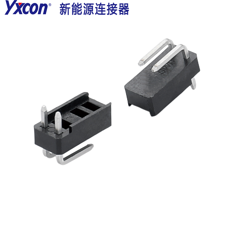
The most notable structural feature of this connector is the combination of its unique outer-post connector design and U-shaped connector terminals. The outer-post design enhances the mechanical strength of the connector, making the installation process more secure and effectively eliminating the risks of cold solder joints and detachment. The U-shaped contact structure greatly improves insertion and extraction stability and effectively prevents loosening caused by vehicle driving vibration. The product offers a variety of pin count options from 1P to 7P. This flexible selection scheme can perfectly adapt to the needs of different circuit designs, whether for simple sensor connections or complex control module interconnections, an appropriate specification can be found.
Technical Specifications and Material Characteristics
A thorough understanding of the technical parameters of the FH2.54-8.5 series connectors is the foundation for ensuring stable operation in specific applications. The electrical performance of this SMT connector has been rigorously designed, with a rated voltage of 12V and a rated current of 1.0AMP, making it highly suitable for the low-voltage DC circuits commonly found in automotive electronic systems. In terms of insulation performance, the withstand voltage test standard of this connector is AC 100V/minute, the minimum insulation resistance is 1000MΩ, and the maximum contact resistance is 20mΩ. These parameters jointly ensure the purity and safety of signal transmission and prevent short circuits and signal attenuation.
In terms of material selection, this automotive connector reflects the requirements of automotive-grade quality. Its plastic material is PA66, an engineering plastic with excellent heat resistance and mechanical strength, which can ensure that the connector does not deform in high-temperature environments. The terminal material is brass, which has good electrical conductivity and elasticity and is an ideal choice for manufacturing precision terminals. Regarding the operating environment, the operating temperature range of this connector covers -55°C to 125°C. This wide temperature range enables it to adapt to various extreme temperature-changing environments in the automotive engine compartment, chassis, and cabin, ensuring that the connector can maintain stable physical and chemical performance whether in severe cold winter or hot summer.
Structural Design and Stability Mechanism
The structural design of the FH2.54-8.5 connector is the key to its high reliability. As a connector with outer posts, the design of its external reinforcement posts is not only to increase mechanical strength but also to provide better positioning and support during the SMT placement process. During the reflow soldering process, these outer posts can help the connector resist deformation caused by thermal stress and ensure the accuracy of solder joint positions. At the same time, after the connector is combined with the PCB board, the outer post structure forms an additional mechanical anchoring point, greatly enhancing the connector's ability to resist vertical pulling force and lateral shear force, which is crucial for the automotive environment that is often subject to vibration.
Complementing the outer-post design is its U-shaped connector terminal structure. The U-shaped terminal design can provide multi-point contact or surface contact. Compared with traditional pin contact, the U-shaped structure can provide more uniform contact pressure during insertion and extraction, thereby ensuring the stability of contact resistance. When subjected to vibration, this structure can use its own elastic deformation to absorb energy rather than directly transmitting stress to the solder joints, thereby effectively preventing solder joint fatigue fracture. In addition, the U-shaped interface design also facilitates the insertion guidance of cable connectors, reducing the alignment difficulty during installation and improving assembly efficiency.
Pre-Installation Preparation
Before starting the installation of the FH2.54-8.5 1-7P SMT with Outer Post U-Shape Automotive Connector, sufficient preparation work must be done. First, confirm that the specifications of the connector you have purchased are fully consistent with the circuit design drawings, including pin count (1P to 7P), pitch (2.54mm), and height (8.5mm). Check whether the connector body has physical damage, especially the outer posts and U-shaped terminal parts, and ensure there is no bending or breakage. At the same time, prepare the corresponding PCB board and confirm that the pad design on the board meets the SMT placement requirements. The pad spacing should precisely match the connector pins, and the surface should be clean and free of oxidation.
Second, check whether the production environment meets the requirements of the SMT process. Since this is an SMT connector, reflow soldering equipment is required. Ensure that the temperature profile of the reflow oven is set correctly and can adapt to the heat resistance characteristics of the PA66 plastic material and brass terminals, avoiding plastic melting or terminal oxidation caused by excessive temperature. Prepare the necessary anti-static tools, such as anti-static tweezers, anti-static gloves, and an anti-static workbench mat, because although this connector has a certain withstand voltage capability, in precision electronic assembly, electrostatic protection is always a necessary measure to protect components from hidden damage.
SMT Placement Operation Steps
Accurately placing the FH2.54-8.5 connector onto the PCB board is the core of the entire process. The first step is to print solder paste onto the pads of the PCB board. Use a stencil that matches the size of the connector pins to ensure that the amount of solder paste is moderate and evenly covers the pads. The printing quality of the solder paste directly determines the subsequent soldering effect. Too much solder paste may cause short circuits, while too little may cause cold solder joints. The second step is to use a placement machine or manual anti-static tweezers to place the automotive connector in the correct position on the PCB board. When placing, it must be ensured that the outer-post part of the connector is accurately aligned with the positioning holes or pads on the PCB board, and at the same time ensure that all U-shaped terminal pins are aligned with the corresponding solder paste pads without offset.
The third step is to send the PCB board with the connector placed into the reflow soldering oven for soldering. During the reflow soldering process, closely observe the oven temperature profile to ensure that the temperature is controlled within the tolerance range of the brass terminals and PA66 plastic, avoiding exceeding the 125°C operating temperature limit that could cause material performance degradation. The fourth step is, after soldering is completed, take the PCB board out of the oven and place it in an anti-static area to cool naturally. Do not move the connector during cooling to avoid solder joint cracking caused by thermal expansion and contraction. After complete cooling, perform visual inspection or use AOI (Automated Optical Inspection) equipment to inspect solder joint quality, confirming that all pins are well wetted and there is no bridging.
Soldering Quality Inspection and Testing
After placement is completed, strict quality inspection must be carried out on the FH2.54-8.5 SMT connector. First, perform a visual inspection, focusing on the soldering condition of the connector with outer posts, ensuring that the solder between the outer posts and the PCB board is full and free of cracks. Inspect each pin of the U-shaped connector and confirm that there is no lifting, offset, or cold solder joint. Since the contact resistance requirement of this connector is 20mΩ Max, any minor soldering defect may cause the resistance to exceed the standard, so the inspection must be meticulous. At the same time, check whether the plastic body shows signs of discoloration or deformation due to high soldering temperatures, which would affect the mechanical strength of the connector.
Next, perform electrical performance testing. Use a multimeter or dedicated test equipment to measure the insulation resistance of the connector and confirm that it meets the 1000MΩ Min standard. Perform a withstand voltage test by applying AC 100V for one minute to ensure there is no breakdown or leakage. For the rated current requirement of 1.0AMP, a simulated load test can be used to verify its temperature rise under actual operating conditions. In addition, since this automotive connector is used in vibrating environments, it is recommended to perform a simple mechanical strength test by gently shaking the connector to confirm that it is firmly installed and has no sense of looseness, ensuring that the outer-post design has played its due reinforcing role.
Application Scenarios and Selection Recommendations
Correctly selecting and using the FH2.54-8.5 series connectors requires consideration of specific application scenarios. This SMT connector is widely used in in-vehicle navigation systems to connect the main control board with the display screen or external modules. In instrument cluster applications, it is responsible for transmitting various sensor signals, and the stable contact characteristics of its U-shaped connector ensure the accuracy of data readings. For headlight control modules, the connector needs to operate in the high-temperature environment of the engine compartment, and its operating temperature range of -55°C to 125°C is fully capable. In body electronic systems, such as door and window control and seat adjustment, the vibration resistance of the connector is particularly important, and the outer-post design plays a key role here.
When selecting, engineers should determine the pin count according to the number of signals required by the circuit, ranging from 1P to 7P. If board space is limited and automated production is required, SMT connectors are the first choice because they support high-speed placement. Considering the complexity of the automotive environment, it must be confirmed that the rated voltage of 12V and current of 1.0AMP of the selected connector meet the load requirements. If the application environment involves frequent insertion and extraction operations, the insertion and extraction stability provided by the U-shaped connector structure will be an important consideration. In short, only by comprehensively evaluating electrical requirements, mechanical strength requirements, and space constraints can the most suitable FH2.54 pitch connector specification be selected.
Maintenance and Storage Precautions
In order to ensure the performance of the FH2.54-8.5 1-7P SMT with Outer Post U-Shape Automotive Connector during storage and use, correct maintenance specifications must be followed. In terms of storage, the connector should be placed in the original anti-static packaging bag and stored in a dry, ventilated environment free of corrosive gases. The storage temperature should be controlled within room temperature range, avoiding direct sunlight and extreme high temperatures to prevent aging of the PA66 plastic material or oxidation of the brass terminals. Since this connector is a precision component, avoid heavy pressure during stacked storage to prevent deformation of the outer posts or damage to the U-shaped terminals, which would affect subsequent placement accuracy.
During use, although this automotive connector is designed for harsh environments, extra care should be taken during repair or rework. If the connector needs to be removed, professional heating equipment should be used to heat the solder joints evenly to avoid damaging the plastic body due to local overheating. When cleaning the PCB board, avoid using strongly corrosive solvents that come into contact with the connector. If slight deformation of the U-shaped terminals is found after installation, do not forcibly correct it; replace it with a new one, because once the elastic characteristics of the terminals are damaged, it will directly affect contact resistance and connection reliability. Following these precautions can maximize the automotive-grade quality advantages of this SMT connector and ensure the long-term stable operation of automotive electronic systems.


