
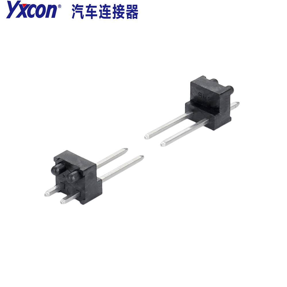
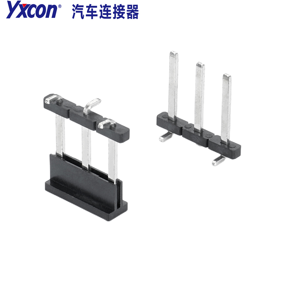
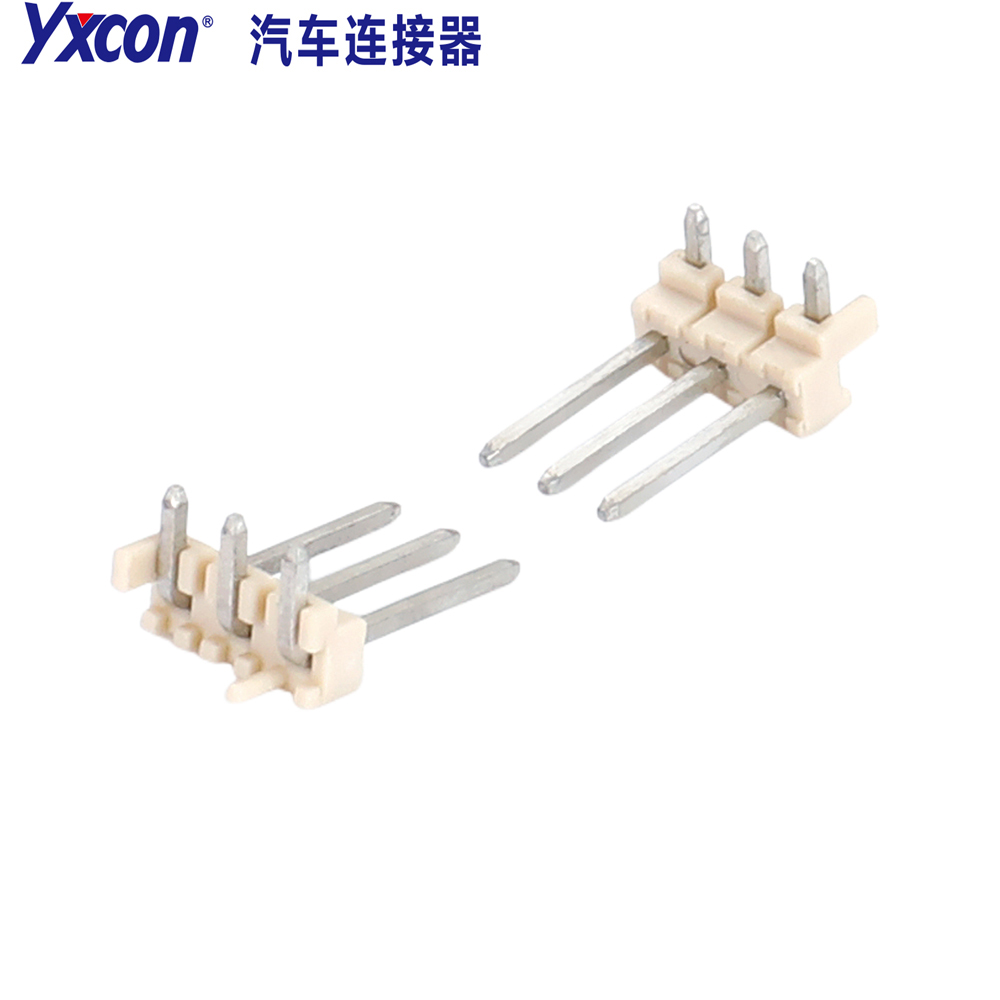
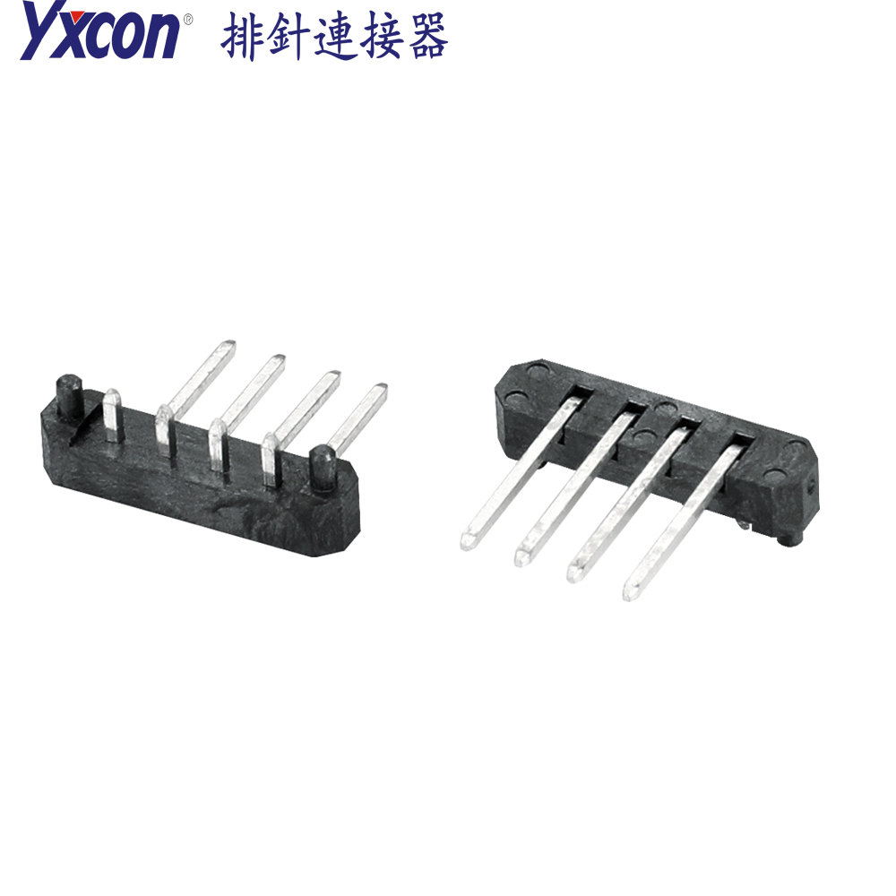





Understanding 2.0DIP and the Two-Piece Structure
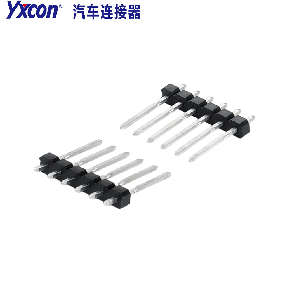
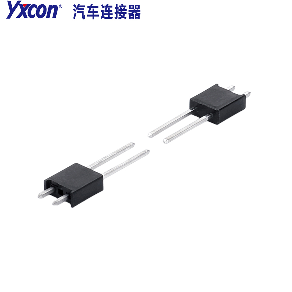
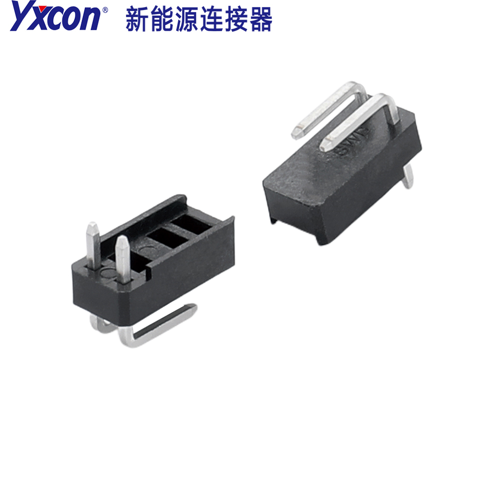
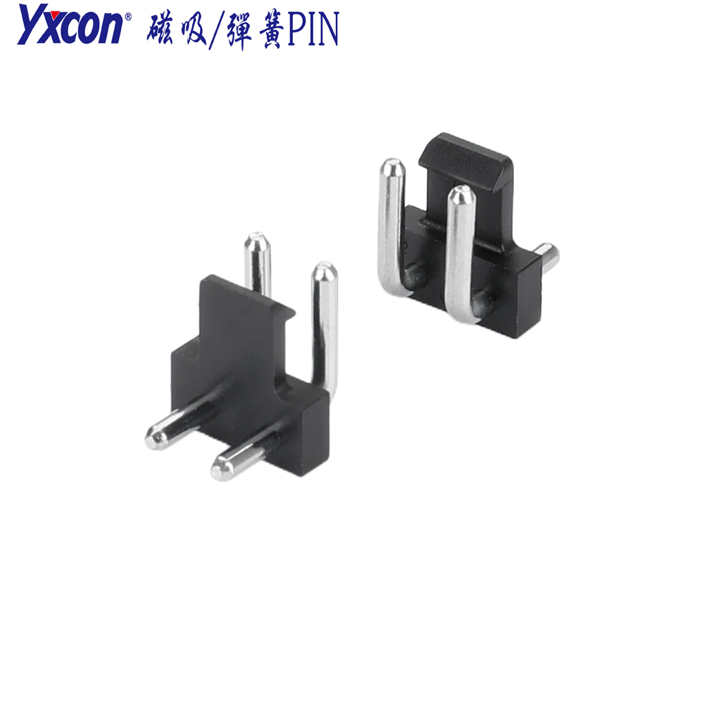
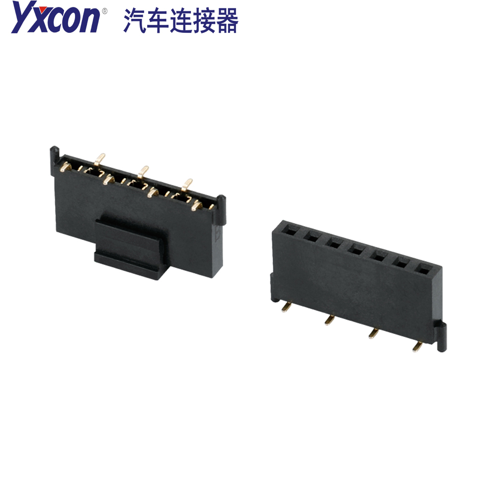
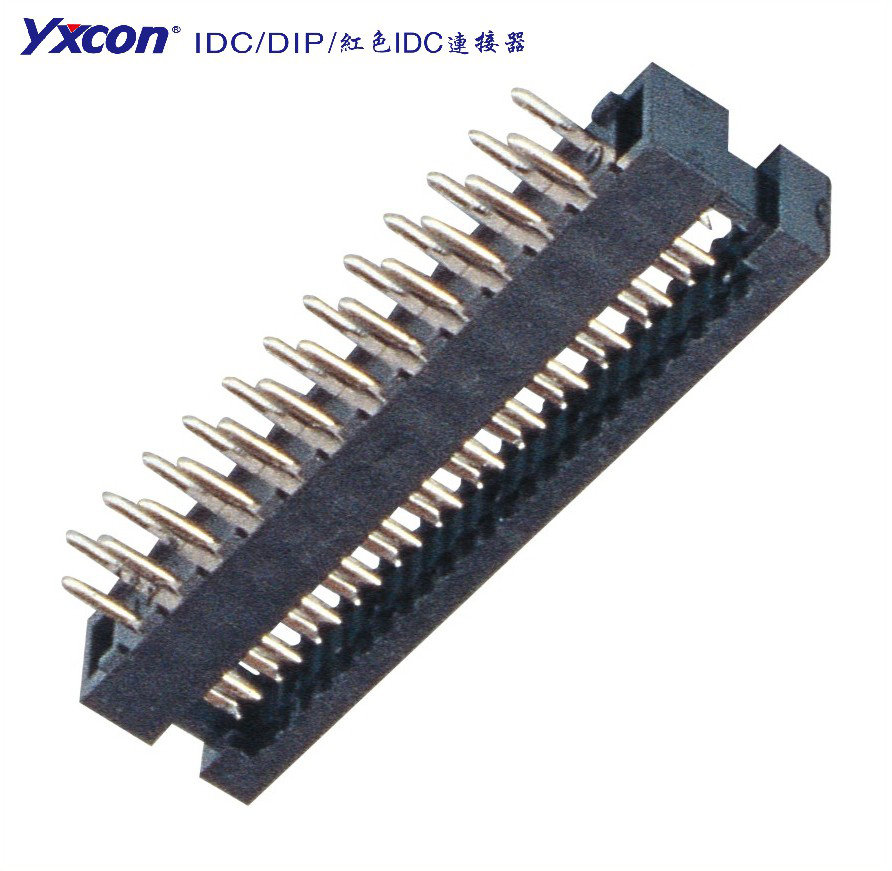
2.0DIP is a category of DIP connector products with a basic pitch specification of 2.0 mm. The products covered in this guide feature a two-piece structure, that is, a combination of 2.0DIP and a two-piece design. In practical applications, 2.0 board-mount DIP and two-piece DIP are often used to refer to the same type of connector solution that has board-mount characteristics and consists of two mating parts. Understanding this naming relationship is the prerequisite for subsequent selection and installation work. The core value of the two-piece structure lies in splitting the connector into two parts that can be handled separately, making installation, maintenance, and replacement more flexible, and this is particularly evident in the 2.0DIP series.
From the perspective of product attributes, the number of positions of this type of connector covers 8~50p, and the height is 3.0 mm. The number of positions determines the range of available connection points; the span of 8~50p means that the same series can accommodate various needs from fewer signals to more signals. The height of 3.0 mm is a dimensional parameter that needs to be taken into account at the layout stage, as it directly affects the space occupied by the component on the board surface and its mating relationship with other parts. Grasping these two attributes is the basis for judging whether 2.0DIP, 2.0 board-mount DIP, or two-piece DIP fits a specific scenario.
It should be emphasized that the two-piece nature of two-piece DIP is not a simple description of quantity, but a way of organizing the structure. The two mating parts each perform their respective functions and, when combined, form a complete connection path. For this reason, when reading this guide, 2.0DIP should always be regarded as an overall system in which two parts work together, rather than viewing either part in isolation. The following sections will unfold around this understanding, gradually explaining the complete process of preparation, operation, and inspection.
Preparation Before Operation
Before starting installation, first confirm that the number of positions of the selected 2.0DIP product falls within the 8~50p range and matches the actual number of connection points required. Insufficient positions will make it impossible to complete all connections, while too many positions may cause waste in layout. At the same time, verify whether the height parameter is 3.0 mm and confirm that this height does not conflict with surrounding components and the overall space arrangement. For 2.0 board-mount DIP, the board-mount installation method has corresponding requirements for board openings and layout, which should be checked and confirmed in advance.
Prepare the two-piece components that match the two-piece DIP, and confirm that both mating parts are complete and match each other. The integrity of the two-piece DIP directly affects the final connection result; without either mating part, an effective connection cannot be formed. Check the appearance of the components and confirm that there are no obvious defects that would affect installation. Place the tools and auxiliary materials required for installation together within reach, to avoid interrupting the process midway to look for tools.
Clarify the installation position and orientation. Mark the placement area of the 2.0DIP on the board surface and confirm that the orientation is consistent with the subsequent wiring plan. For 2.0 board-mount DIP, once the board-mount orientation is determined, the cost of subsequent adjustment is relatively high, so the orientation issue should be thought through once and for all at the preparation stage. After completing the above checks, proceed to the formal installation steps, which can effectively reduce rework.
Step-by-Step Installation Procedure
Step 1: Position and secure the first mating part. Place the first mating part of the two-piece DIP onto the marked position and align it according to the pitch specification of 2.0DIP. When aligning, use the arrangement of the number of positions as a reference and confirm the position one by one. Keep the part stable during securing to avoid affecting the insertion of the second mating part later due to tilting. The dimensional feature of 3.0 mm height should remain visible at this stage for easy verification at any time.
Step 2: Install the second mating part and complete mating. Align the second mating part of the two-piece DIP with the secured first part and insert it smoothly along the established direction. During insertion, pay attention to the relative positions of the two parts to ensure proper mating rather than forced assembly. For 2.0 board-mount DIP, the board-mount action should be completed in one go to avoid unnecessary wear caused by repeated insertion and removal. After mating is completed, check whether there are obvious gaps or misalignment between the two parts.
Step 3: Verify the number of positions and the overall state. Against the position range of 8~50p, confirm that the number of points actually used is consistent with the design, and that unused points remain in their proper state. Observe whether the 2.0DIP as a whole is flush and whether the height is the expected value of 3.0 mm. Confirm that both mating parts of the two-piece DIP are in the correct positions and that the connection relationship is stable. At this point, the main installation operation is complete, and the inspection stage can begin.
Key Operating Points and Precautions
When operating 2.0DIP, always treat the two-piece structure as a whole. The two mating parts of the two-piece DIP have a clear mating relationship, and adjusting one part alone often destroys the established mating state. If adjustment is truly necessary, first separate the two parts, adjust them, and then re-mate them, rather than forcibly prying them while mated. This principle also applies to 2.0 board-mount DIP; forced changes in the board-mounted state can easily create hidden risks.
Pay attention to the timing of verifying the two attributes of number of positions and height. Confirmation of the 8~50p number of positions should be completed before installation, with only a recheck after installation; verification of the 3.0 mm height should run throughout the entire installation process, because height deviations often only become apparent after mating is completed, at which point the cost of handling is higher. For two-piece DIP, it is recommended to perform a brief state confirmation after each step to detect problems early.
Avoid forced insertion without confirming the mating orientation. The mating of 2.0DIP is directional, and forced operation when the orientation is wrong is a common source of problems. If obvious insertion resistance is encountered, stop and recheck the orientation and alignment state rather than increasing force. Keeping the operating environment clean and preventing foreign matter from entering the mating area is also a basic requirement for ensuring the connection quality of two-piece DIP.
Post-Installation Inspection and Confirmation
After installation is completed, perform an overall inspection of the 2.0DIP. Confirm that both mating parts of the two-piece DIP are in place, that the mating relationship is stable, and that there are no signs of looseness. Verify whether the actual use of the number of positions falls within the expected range of 8~50p, and that unused points are in normal condition. Check whether the height is 3.0 mm and consistent with the pre-installation plan. Record each item during inspection to avoid omissions.
Perform a dedicated confirmation of the board-mounted state of the 2.0 board-mount DIP, observing whether it is fully seated and whether there is any skew. If abnormalities are found, separate first and then adjust according to the above key points; do not continue using it with defects. If anything inconsistent with expectations is found during inspection, trace it back to the specific step and determine whether the problem lies in positioning, mating, or verification, so as to handle it in a targeted manner.
After inspection passes, tidy up the operation site and put away tools and remaining materials. Record the number of positions and height parameters on which this installation was based for future maintenance reference. For two-piece DIP, recording the mating state and installation orientation of the two parts can provide a basis for subsequent inspection and replacement. Complete records are an important guarantee for the long-term stable use of 2.0DIP.
Common Problems and Handling Approaches
When 2.0DIP has improper mating, first go back to the alignment step for troubleshooting. The mating of two-piece DIP depends on the precise alignment of the two mating parts, and any offset on either side will cause mating difficulty. When handling, first separate the two parts, realign them, and then insert them again, avoiding repeated attempts while in the mated state. For 2.0 board-mount DIP, verification of the board-mount orientation should take priority over other troubleshooting items.
When the actual state of the number of positions or height does not match expectations, distinguish whether it is a problem at the selection stage or the installation stage. The 8~50p number of positions is a selection parameter; if it does not match actual needs, it must be re-evaluated from the selection stage. If the 3.0 mm height deviates after installation, it is mostly related to operations during installation. Only by distinguishing the source of the problem can the correct handling path be chosen, rather than blindly adjusting.
For two-piece DIP, if a problem is suspected with one mating part, first confirm the state of the other part, and then determine which part the problem belongs to. One of the advantages of the two-piece structure is that the parts can be inspected and handled separately. Remain patient during handling and eliminate items one by one, avoiding changing multiple links at the same time and complicating the problem. Recording the process and results of each handling helps accumulate experience.
Expected Results and Subsequent Maintenance
After completing operations according to this guide, a properly installed 2.0DIP should be obtained: the two mating parts of the two-piece DIP are correctly mated, the number of positions is used as needed within the 8~50p range, and the height remains 3.0 mm. The board-mounted state of the 2.0 board-mount DIP is stable, and the overall layout is consistent with the pre-installation plan. Inspection records are complete, leaving a basis for subsequent use and maintenance.
During subsequent maintenance, regularly recheck the mating state of the two-piece DIP and confirm that there is no looseness or offset. Verify whether the usage of the number of positions has changed and whether the height is still 3.0 mm. For 2.0 board-mount DIP, pay attention to the stability of the board-mounted portion. During maintenance, follow the same principles as installation: separate first and then adjust, and do not forcibly change the mating state.
File the relevant parameters and operation records of 2.0DIP, 2.0 board-mount DIP, and two-piece DIP together to form traceable documentation. In this way, when replacement or expansion is needed, historical information can be retrieved quickly, reducing the workload of repeated verification. Only by combining standardized operation with complete records can the two-piece DIP solution play its due role in practical applications.


