






Product Overview and Core Parameters
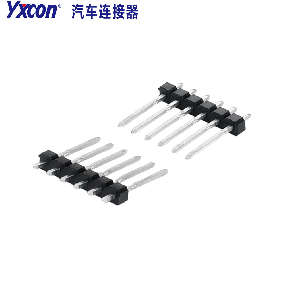
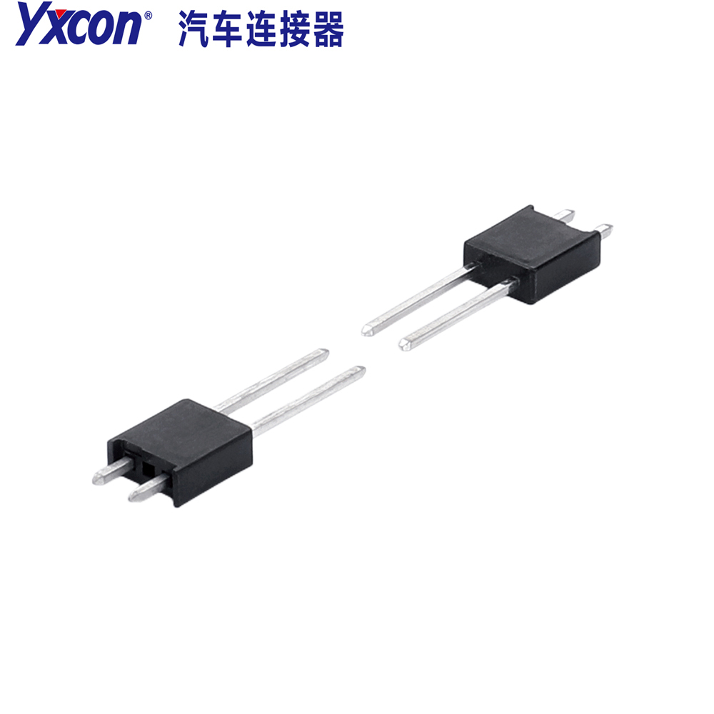
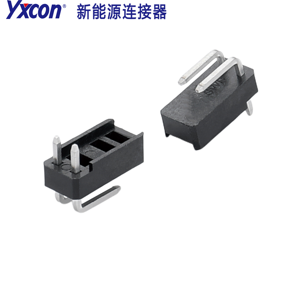
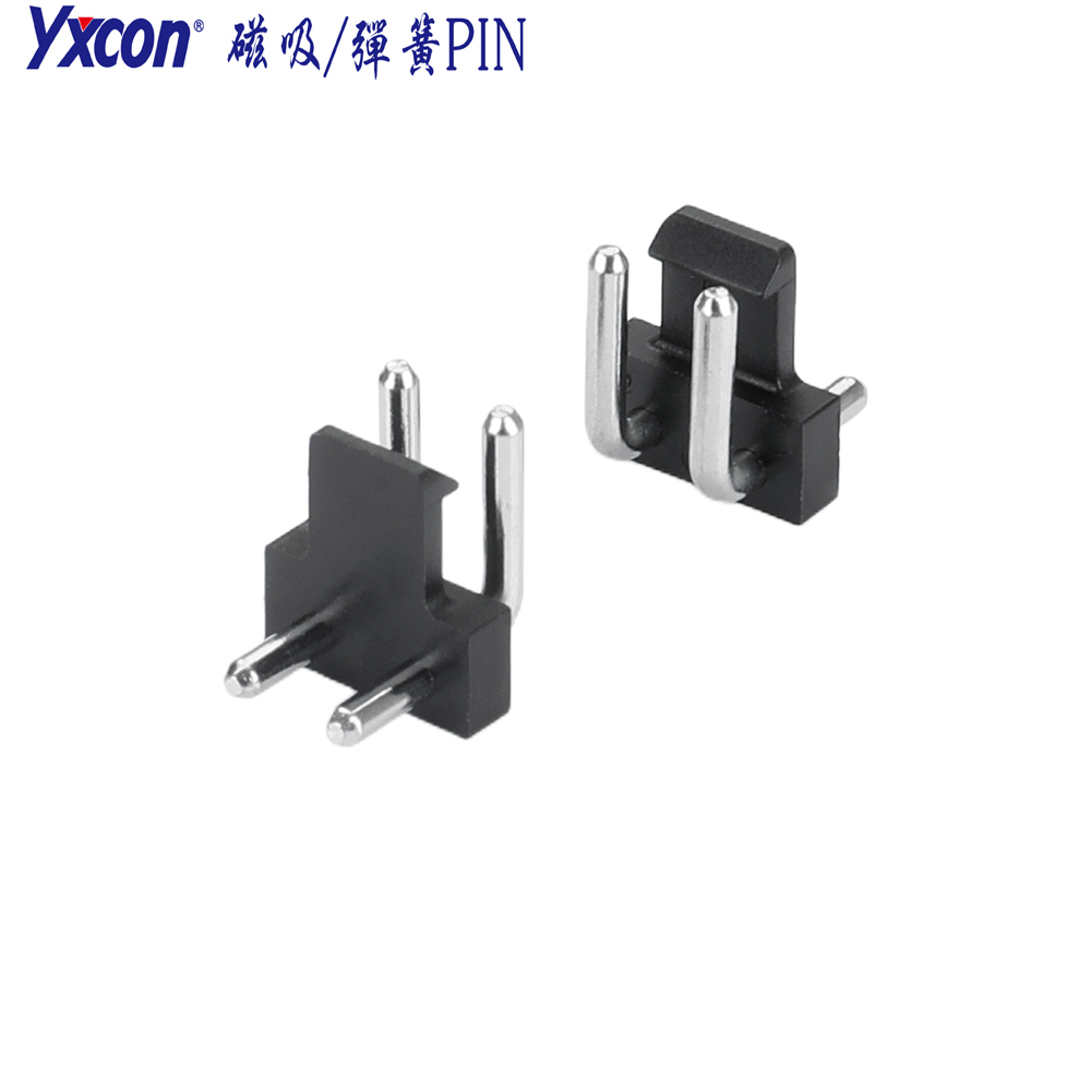
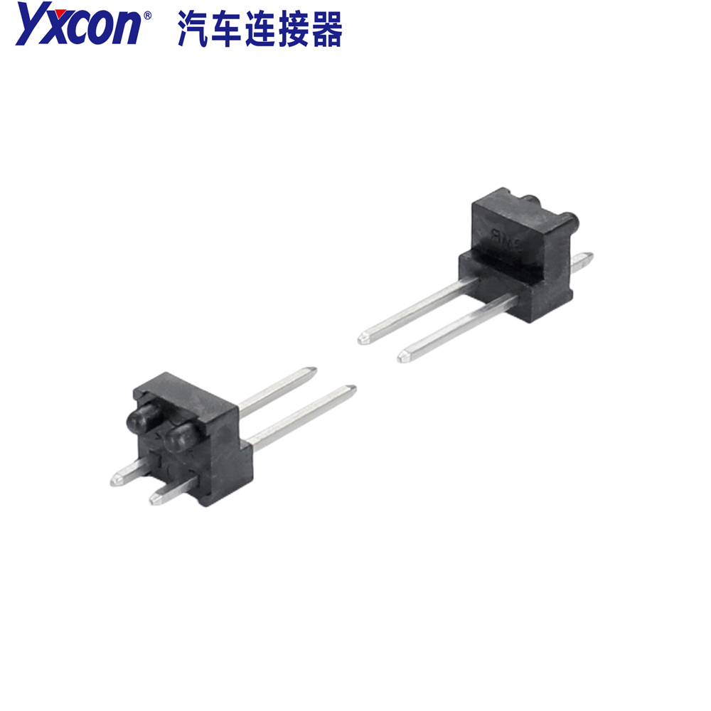
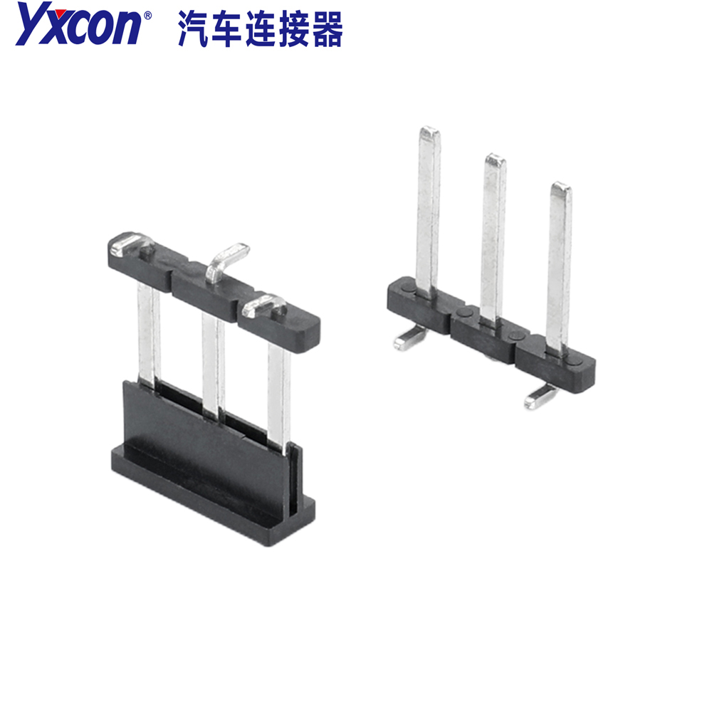
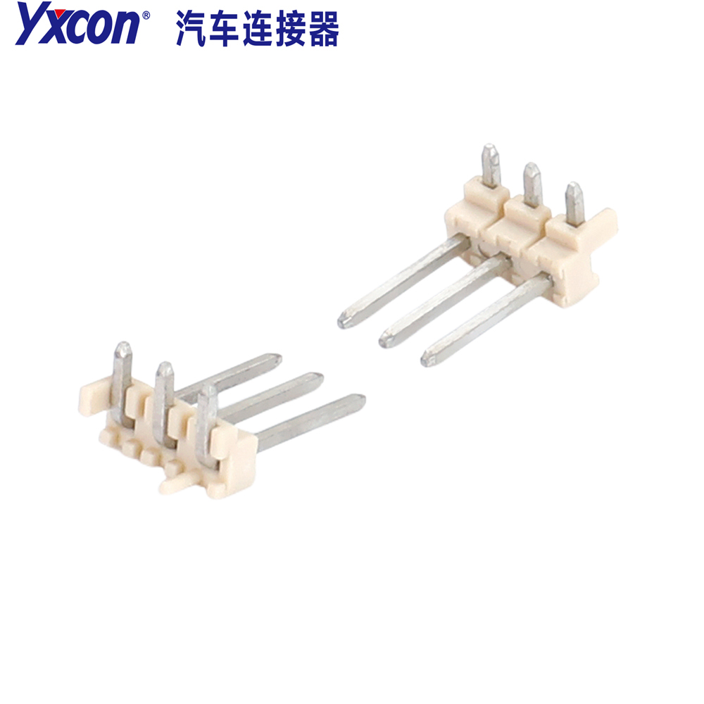
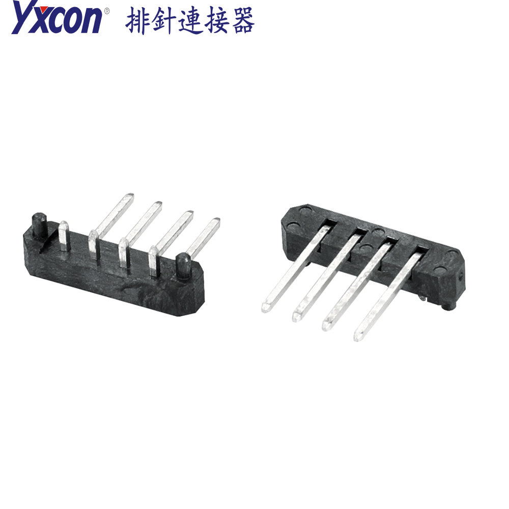
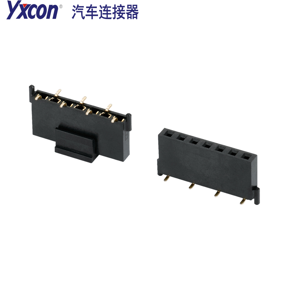
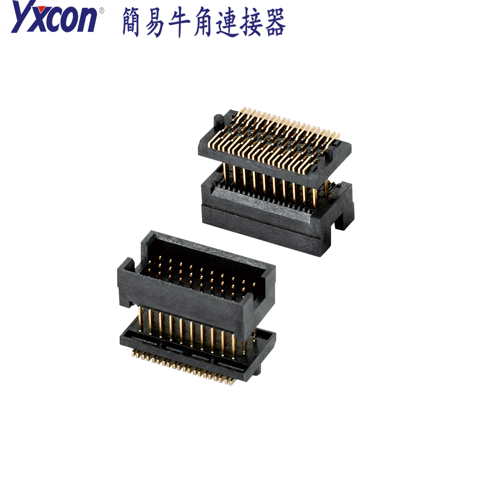
This 1.27mm pitch four-row simple horn connector, combined with a dedicated simple horn heightening cover design, precisely controls the overall height at 11.23mm, providing a stable structural foundation for high-density board-end connections. The product name is 1.27 four-row simple horn connector plus simple horn heightening cover, with the Pin count marked as XXP; the specific Pin count is selected according to actual requirements. This product belongs to the four-row specification in the XXP simple horn series, with four rows, and the SMT end mounting height is 8.3mm, suitable for automated placement and reflow soldering processes.
The four-row simple horn adopts a 1.27mm pin pitch, with compact pin arrangement, which can greatly save circuit board space and is suitable for precision connection scenarios. The simple horn heightening cover serves to increase height and provide protection, enabling the 11.23mm total height simple horn to meet specific installation height requirements, while also providing dustproof, vibration-resistant, and terminal protection functions. Users should first confirm whether the pitch, number of rows, total height, and SMT end dimensions in the product drawing are consistent with the design documents before proceeding to the subsequent installation process.
Pre-Installation Preparation and Material Verification
Please verify the connector model in the bill of materials, confirm that the purchased product is the 1.27 four-row simple horn connector plus simple horn heightening cover, and check whether the Pin count on the packaging is consistent with the XXP simple horn specification in the BOM. Please use a magnifying glass or microscope to inspect the four-row simple horn pins for bending, oxidation, or contamination, and confirm whether the simple horn heightening cover is fully engaged on the connector body without lifting or missing.
Please prepare solder paste and stencil according to the reflow soldering temperature profile. When selecting stencil openings, match them according to the actual pin pitch and pad dimensions of the 1.27mm four-row simple horn to ensure an appropriate solder paste printing volume. Please check whether the PCB pads are consistent with the connector pin arrangement, paying particular attention to the positioning orientation of the four-row layout to avoid misalignment of the first pin. Please confirm that the PCB surface is flat and free of debris, and clean the pad area to prevent poor soldering.
Selection and Specification Confirmation Steps
Please confirm the specific Pin count, because XX in the XXP simple horn represents the number of Pins that can be selected according to requirements. Please verify whether the total height of the connector is 11.23mm; if the installation space is more strictly limited, please confirm with the supplier whether the height can be adjusted or other specifications selected. Please check whether the SMT end dimension is 8.3mm, as this dimension directly affects the stencil thickness and placement nozzle selection.
Please select the specific Pin count of the four-row simple horn according to the application scenario. The high-density four-row design is suitable for board-end connection scenarios such as industrial control, communication equipment, medical devices, automotive electronics, and instrumentation. Before ordering, confirm that what is needed is the 11.23mm total height simple horn matched with the SMT 8.3mm simple horn end face dimensions, to avoid confusing ordinary simple horns with simple horn heightening cover combinations. If other heights, row counts, or customized specifications are required, please clearly state them in the order remarks.
SMT Placement and Soldering Operation Guide
Please place the connector into the automatic placement machine feeder, and set the nozzle model and placement pressure according to the material dimensions. Before placement, please confirm that the bottom pins of the four-row simple horn are precisely aligned with the PCB pads, and use the machine vision system to check the first pin marking to prevent rotation or offset. Please set an appropriate placement height so that the bottom surface of the SMT 8.3mm simple horn pins contacts the solder paste on the pads, but do not press down excessively to avoid damaging the simple horn heightening cover or pins.
Please set the reflow soldering temperature profile according to the solder paste characteristics. Please ensure that the preheat zone heats up gently to avoid thermal shock to the simple horn heightening cover and high-temperature-resistant insulating material. In the reflow zone, please control the peak temperature and time so that the solder joints of the four rows of pins melt fully and wet well. After cooling, please check whether the solder joints are bright and full; if the solder volume is insufficient, the stencil openings can be adjusted, but manual solder addition should not be performed to avoid affecting solder joint consistency.
Simple Horn Heightening Cover Assembly and Height Verification
Please check whether the simple horn heightening cover is still firmly fixed to the connector after reflow soldering. If the heightening cover has shifted, please first confirm whether it was affected by external force or high-temperature deformation during the soldering process. Please use a height gauge to measure the total height of the connector to verify whether it meets the 11.23mm installation requirement, and also measure whether the SMT end dimension remains 8.3mm. If the height exceeds the tolerance, please check the cumulative error of the PCB thickness and solder paste thickness.
Please place the assembled board into the complete device housing for a trial fit, and confirm that the simple horn heightening cover fits smoothly with the mating part without interference or jacking. If it is found that the 11.23mm total height simple horn cannot be inserted into the mating connector, check the mating part height and keying orientation. Please avoid forced pressing to prevent damaging the four-row simple horn pins or the heightening cover. During use, the simple horn heightening cover can also prevent dust from entering the terminal area and reduce the impact of vibration on solder joints.
Quality Inspection and Testing Process
After soldering is completed, please use AOI equipment to perform automatic optical inspection on the four-row simple horn pins, focusing on bridging, insufficient solder, and offset defects of the four rows of pins. Please use a multimeter or flying probe test to confirm the continuity of each Pin, and verify whether all pins of the XXP simple horn correspond one-to-one with the PCB nets. For the 11.23mm total height simple horn, also check whether there is residual flux or solder balls under the heightening cover to avoid short-circuit hazards.
Please perform an insertion and extraction test, using a standard mating connector with the four-row simple horn for multiple insertions and extractions, to confirm reliable contact without looseness. Please record the test results; if abnormal contact resistance occurs, check whether the SMT 8.3mm simple horn solder joints are cold soldered or whether the pins are deformed. After all tests are completed, please store the board in a dry and clean environment to prevent the simple horn heightening cover and terminals from moisture and oxidation.
Precautions for Use and Maintenance Recommendations
Please handle with care during transportation and assembly, and do not touch the simple horn heightening cover and four-row simple horn pins with sharp tools. Please avoid exposing the connector to environments exceeding the material's temperature resistance range, because although the high-temperature-resistant insulating material can withstand reflow soldering temperatures, long-term high temperatures may affect the dimensional stability of the simple horn heightening cover. Please regularly check whether the installed 11.23mm total height simple horn is loose or displaced, especially in industrial control or automotive electronics scenarios with high vibration.
Please do not insert or extract the connector while powered on, to avoid arcing and damaging the terminals. Please keep the area around the connector ventilated and clean to avoid dust accumulation at the bottom of the simple horn heightening cover. If cleaning is required, please use anhydrous ethanol and an anti-static brush; do not use strong acid or strong alkali solvents. After maintenance, please reconfirm that the SMT 8.3mm simple horn solder joints have no cracks and that the Pin count is correct, ensuring stable long-term signal transmission of the XXP simple horn.
Ordering and Customization Tips
Please confirm the Pin count according to actual requirements, and specify the specific value of the XXP simple horn in the order, such as 20P, 30P, or other available options. Please also specify that what is required is the four-row simple horn plus simple horn heightening cover combination, with a total height of 11.23mm and an SMT end dimension of 8.3mm, to avoid confusion with other specifications. If other heights, row counts, or customized specifications are required, please contact the supplier in advance to confirm the lead time and minimum order quantity.
Please request the product drawing and footprint library files before ordering, and verify whether the pad dimensions and the mechanical dimensions of the 11.23mm total height simple horn are suitable for the existing PCB layout. Please confirm whether the packaging method is suitable for automatic placement machines; if it is bulk or tube packaging, evaluate the feeding stability. After completing the above confirmations, please submit the purchase order in the format required by the supplier, attaching the material code and technical requirements, to ensure that the delivered 1.27 four-row simple horn plus simple horn heightening cover meets the design expectations.


